
Ableworks' solutions and technology blog pages offer a wide range of technical articles on smart meters, smart IOT, and batteries. We provide in-depth coverage of innovative smart meter solutions and smart IOT technologies, and we also share battery trends and specialized knowledgebases. Read our blogs to build your future knowledge and gain insight into our ongoing research and development.
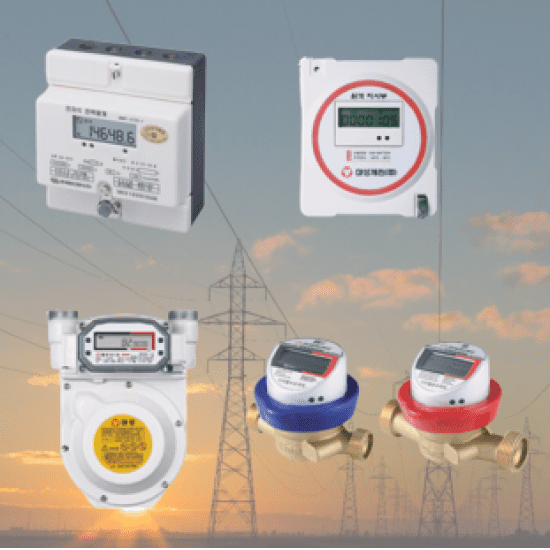

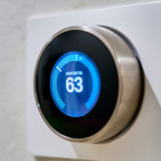
Ableworks specializes in providing component supply and technical consulting services for applications mainly in the fields of SMART METER, BATTERY, and SMART IOT. This enables our customers to develop and bring innovative products to market utilizing advanced technologies. Ableworks' expertise is based on in-depth knowledge and experience across various aspects of the industry, which provides excellent opportunities for cooperation.
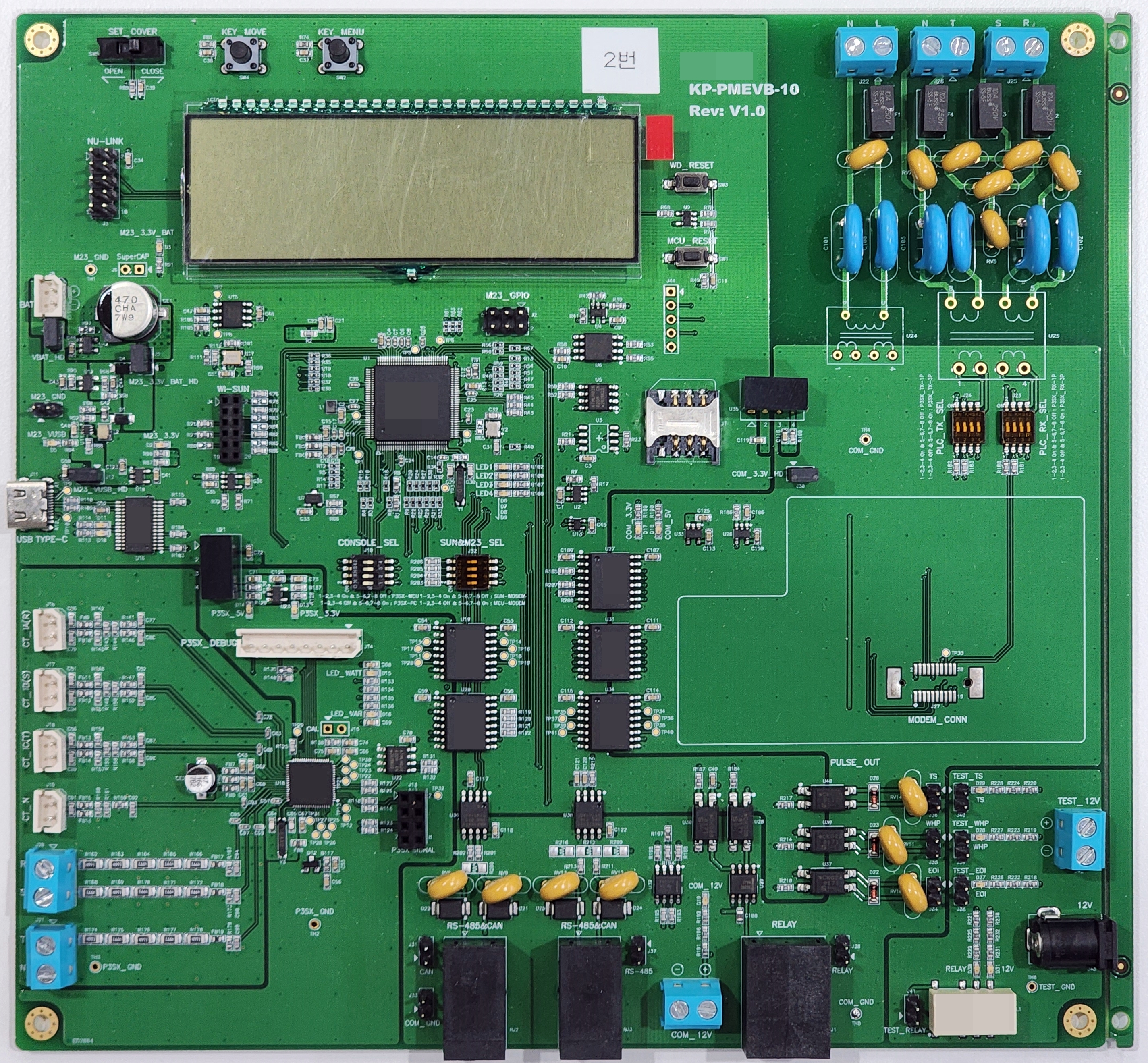
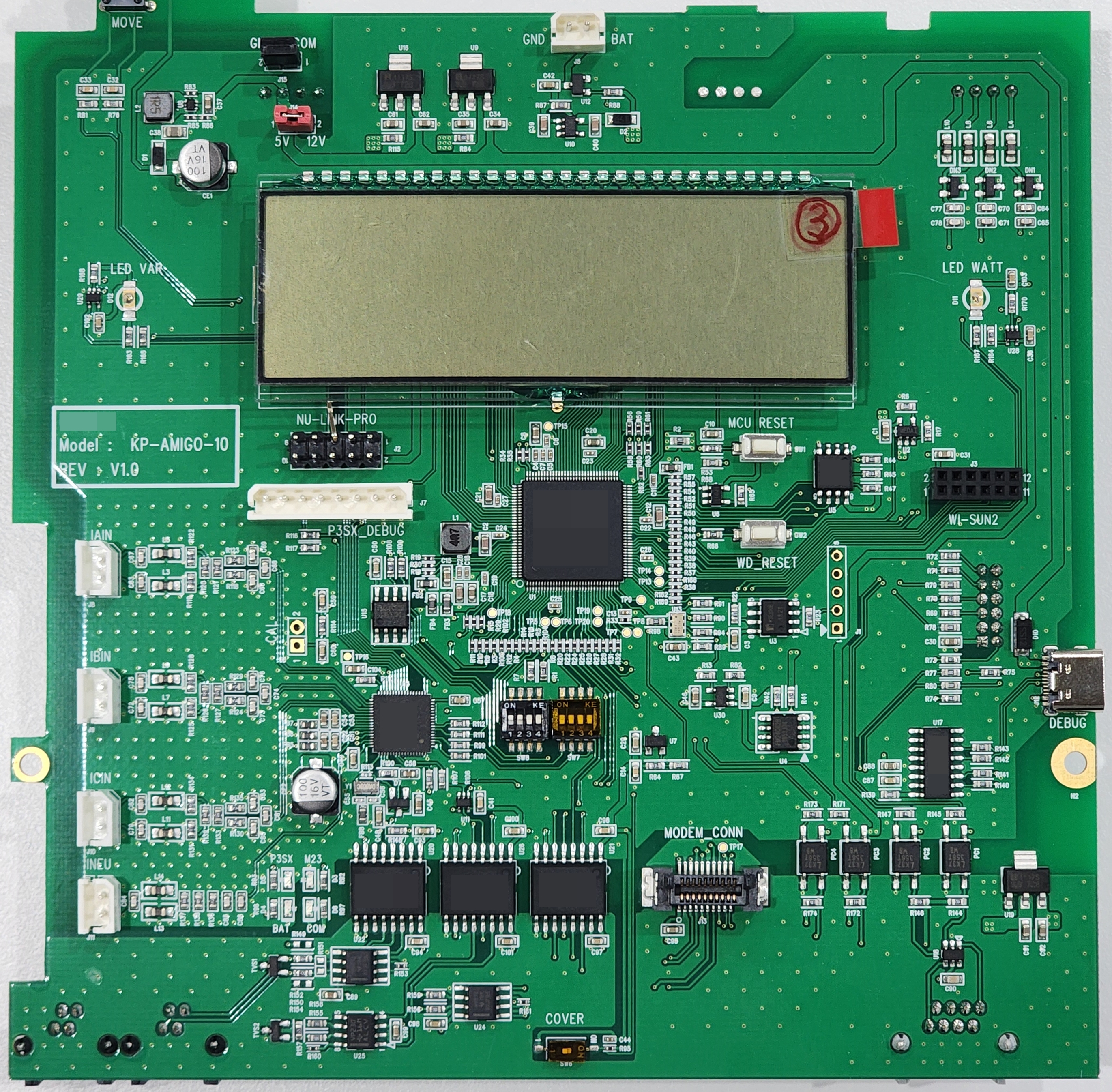
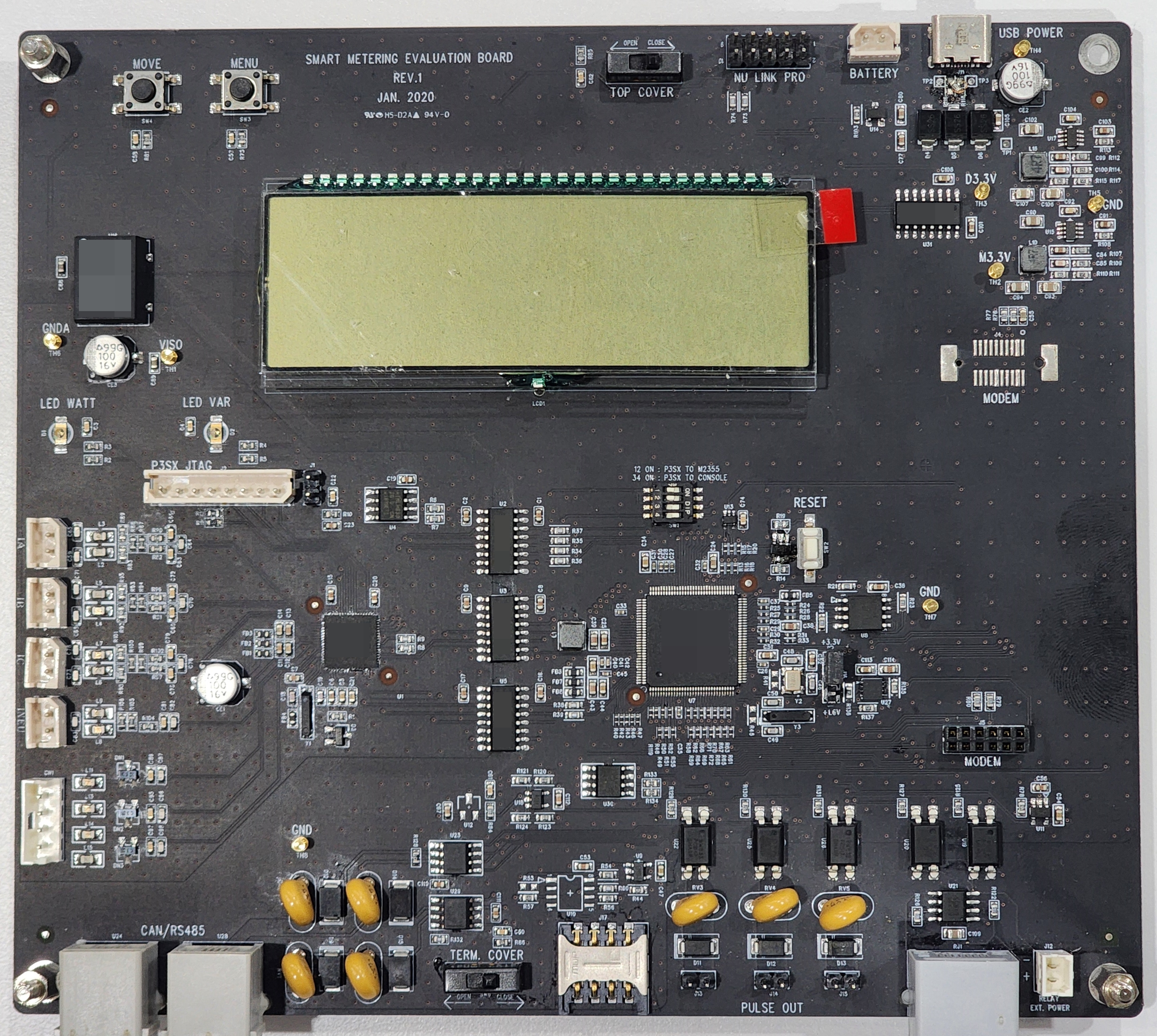
Power Meter is composed of KCMVP security chip, relay, battery, LCD, CT, RTC, Wi-Sun, centered on the metering MCU.
Power Meter board requires parts such as main MCU, KCMVP security chip, Load Switch, Isolator, RS-485 Tranceiver, LCD, Relay, Relay Driver, Battery, Voltage Detector, EEPROM, CT, RTC, etc. and Ableworks is supplying the parts and design consulting.
The Power Meter development board, designed by AbleWorks, helps customers develop and mass-produce faster and more conveniently, and can be seen in the photo on the left.
Amigo.jpg)
The block diagram shows a unidirectional AMIGO board. This board is differentiated from the development board by being designed to be closer to the product. The main components include a main MCU with an RTOS and a metering chip responsible for power metering. The main MCU area contains CAN, RS-485, Wi-SUN communication modules, KCMVP security chip, EEPROM, and connections to the LCD.
The metering chip part is responsible for processing the power measurement data input from the CT through analog front-end logic and passing it to the main MCU. With this configuration, the board provides the product with a harmonious function and form, and realizes efficient data processing and communication in various areas.
Smart Meter.jpg)
Here is a block diagram of a lightweight smart meter. This system is different from the KEPCO-oriented AMIGO, effectively integrating the power metering part, KCMVP security chip, communication module, real-time clock (RTC), relay, battery, and LCD in one Metering MCU. This design has the advantage of forming a lighter system than AMIGO. This allows for a lightweight and efficient system configuration.
Smart Switch.jpg)
A smart switch system consists of a main controller, switching circuits, wireless communication modules, power management circuits, and device status display functions. The main controller manages various tasks and coordinates switch state management. The switching circuit controls power flow and performs electrical connection and disconnection tasks, and the wireless communication module communicates with external devices and connects with the smart home system.
Smart Gas Meter.jpg)
The internal system block diagram of a smart gas meter consists of the following main components. The main MCU, which is the main axis, coordinates the various functions and drives data processing and communication. Precise gas metering is achieved through the gas metering module, while the communication module utilizes wireless technology to transmit usage data. To ensure user data security, the security module plays an important role. Power management and backup batteries support continuous operation, while displays and UI help provide convenient information to users. Including modules for data storage and time management, and sensors and detectors, smart gas meters play a key role in energy management through efficient and accurate data collection.
Multi-Jet Water meter.jpg)
The internal system block diagram of a multi-jet water meter has the following main organization. The main MCU drives the data processing, communication, and metering tasks, while the multi-jet metering module is responsible for accurate water flow metering. The data communication module transmits water usage and meter status data externally. Power management and backup batteries ensure continuous operation of the meter, while the display and UI visually communicate information to the user. Finally, the flow detection sensor performs accurate water flow detection. Together, these elements enable the multi-jet water meter to collect accurate data, provide valuable information, and efficiently manage water usage.
Water meter AMI.jpg)
The internal system block diagram of a water meter equipment system consists of various legacy elements. The main ones are the water meter main MCU unit, sensor module, wireless or wired communication module, security and encryption, display and UI, and battery.
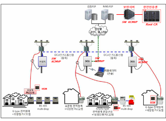
Establishment of KEPCO Certification Center (CA)
- Certificate management authority, creation, disposal, renewal, and operation is KEPCO Information Security Office
Security server development/installation
- Verify that terminated devices are legitimate devices of KEPCO
DCU/Modem (communication device)
- SW KCMVP is applicable to devices with OS (Linux or Window), HW KCMVP is also applicable Communication method LTE, RS-485, HSPLC, HPGP
Power meter (end device)
- Security must be applied to realize true end-to-end security. Application of KCMVP
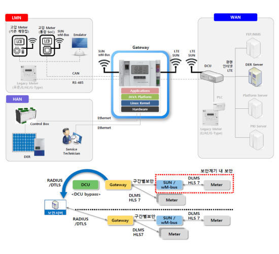
Smart meter gateways play an important role in harmoniously interconnecting various data flows between LMN, HAN, and WAN. As a key element for this, the gateway has a built-in KCMVCP security module that provides excellent safety. This module ensures the safety of sensitive information by thoroughly encrypting data, while also facilitating the authentication process for data authenticity.